Articles
Electric Shock Case Study 1: The Jumbo Tingle at an Underground Mine
As world-recognised experts in safe power system earthing/grounding and lightning protection systems, Safearth are often called to investigate electric shock incidents around the globe. Each incident is different, sometimes tragic and we can never be certain what we may find. The consulting team always learn something new from attending these instances which helps us build on our experience and help prevent electric shocks in the future. In this series of articles we will cover two recent electric shock scenarios, the mechanisms, and recommended actions.
Case Study 1: The Jumbo Tingle at an Underground Mine.
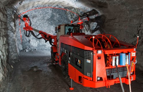
Safearth was commissioned to perform a desktop study into the likely causes of electrical voltage identified at drill rigs (also known as Jumbos) at a mine. This investigation was triggered by information provided to Safearth indicating that voltages were measured in the underground mine between the roof mesh, which was in contact with the earth, and the chassis of rubber tyre drill rig. In some instances, operators had reported a tingling sensation when simultaneous contact was made between the roof mesh and drill rig. The mining regulator had been notified.
From a miner’s perspective this is what happened:
- Hard rock mine operating jumbos.
- Feeling tingles between drill chassis and earth.
- Voltages measured by site electricians. 2-3V normal load. 6-10V during start-up.
- Couldn’t find cause of the shock.
- Temporary solution bonding to ribs.
Background:
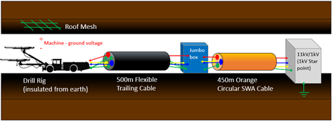
- Mine supplied from 132/11kV Essential Energy Surface Substation.
- The power supply to the drill rig consisted of.
- 11kV stepped down to 1kV IT System
- Orange SWA cable with asymmetrical, earth core.
- Jumbo Box including a 5-way distribution board with cable terminations.
- Trailing cable to drill rig.
- Drill rig on rubber tyres.
- Persistent voltage measured between drill rig and roof mesh, but the source was unknown.
- This was a safety concern and a production risk.
What was known?
Each of the jumbos was:
- 150kVA machine @ 1kV. FLC ~85A
- No variable speed drives
- Voltage between chassis and ground
- 2-3V normal, 6-10V short term
- Mix of 1kV cable types
- Long (~1km) cable run
- Initial report of shock incident led to wider reports at the mine
- Multiple machines involved
- Voltage reduced but not eliminated when jumbo isolated
- Supply sub not directly above
- Earth faults not detected
- No other touch voltage locations on HV system
- Distribution boxes suspended on chains/slings
- No high current parallel transmission lines on surface.
These are the facts we had to work with. What we didn’t know, was whether the fault was persistent. Our job as investigators was to try and work out what’s causing the voltage and then how to fix it.
Possible Causes & Investigation
- Persistent HV Earth Fault
- Distribution Cable Fault
- Unbalanced Load
- Static
- Inductive coupling.
From what we found out we could we rule out some of the possibilities.
- No voltage rise on upstream subs and the 132kV sub is a distance away.
- No unexplained 11kV or 1kV earth faults on the protection system, and the cable insulation intact.
- Imbalanced load not likely: 3 phase loads and relatively well balanced.
- Frequency measured at 50Hz, so not static or high frequency from VSD.
- Could it be induction related?
Root Cause
After deliberating on the facts, we discussed:
- Long items create induction.
- 1km of 1kV cable for EMF to build.
- Induction looking likely.
- But where and how do we fix it?
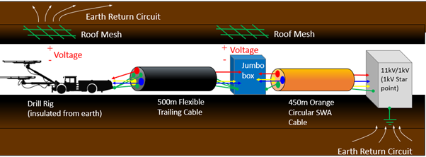
We had two types of asymmetric cables to consider, 241 trailing cable and orange SWA 3c+E. Earth cores in trailing cable are geometrically balanced and each earth core has equal magnetic exposure to each phase. When tied together we experienced no EMF from end to end. In SWA single earth core cable, earth core had geometric imbalance and unequal exposure to magnetic field from each phase. Commonly EMF builds up over distance and can be significant. Cable armour in SWA cable usually reduces geometric imbalance but, in this case, it wasn’t well bonded.
We found that where SWA terminates through a gland that is not well connected, or through paintwork on distribution board, little or no current can flow in the armour. Current in armour helps reduce EMF build up on earth core. In this case, armour was not well bonded and reduced EMC performance of cable.


Pictured: Orange SWA 11kV cable (1) and cable terminations (2 & 3)
Cable Core Induction
- 500m of balanced, 500m unbalanced.
- Essentially creates single winding transformer between phase and earth
- Black line is earth system with reference provided by skid mount transformer. The magnetic imbalance is shown in orange,
- The imbalance induces current in the reverse direction on the outside like a transformer.
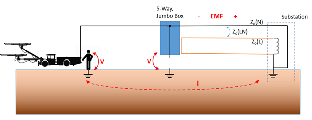
- 5-way board sitting on rock bolts. 100Ohms to ground. Jumbo on rubber tyres. Both are not well bonded earth.
- Voltage found between conductive parts and ground.
Mitigation Options – What can we do about it?
- Cannot eliminate induction without replacing asymmetric 3c+E cable type with symmetric alternative.
- Reduce voltages between metal parts and ground by increasing current flow in cable earth parts
- Bond SWA to distribution boxes and skid mount transformer.
- Bond earth boxes well to mesh
- Implement for all supplies to drill rigs underground.
We couldn’t eliminate the voltage without replacing the asymmetric cable with a symmetric alternative. This wasn’t a short-term option to the mine. Subsequently, we needed to reduce the voltage as far as reasonably possible. To do this we had to increase current flow in the cable earth return paths. This involved bonding the armour, and second, achieving good connections between the jumbos, 5-way distribution boards to the ground. This action increased current flow in the cable screen and earth cores and instead of voltage appearing as open circuit, touchable voltage at the distribution boards and machine, the voltage dropped along the length of the earth cores.
Site Implementation
Once the solution was confirmed the site:
- Cleaned paint off boxes and terminated the cable glands.
- Bonded 5-way and jumbo boxes to the roof mesh and ribs.
- Did that for all asymmetric cables underground.
- Remeasured the voltages.
Through concise investigation, testing and problem solving we were able to significantly mitigate this critical safety issue onsite and help protect future staff from electric shock.
Safearth Consultant: Benton Greive, Senior Engineer