Articles
Technical Article – Earthing Tests: Making the Right Choice
Choosing the Right Tests for Your Assets
What is earthing system testing? There are actually many different tests, each with different purposes and benefits. Dr Darren Woodhouse, Principal Engineer at Safearth, outlines some of the common tests.
Owners of HV assets hold a responsibility for their safe and effective operation from the first day of service through to end of life. While test and maintenance requirements for HV equipment are typically well understood, earthing systems often remain a mysterious unknown. Many high voltage asset owners will engage a consultant or technician to ‘test’ their earthing system – but what does an earthing ‘test’ look like? There are actually a range of investigations that can be performed and depending on what the objective is, a particular test could be perfectly appropriate or alternatively, completely uninformative or perhaps even misleading. Consequently, there is a real risk that poor test information can misguide decision making on safety compliance and earthing maintenance activities.
This article provides an overview of the main earthing test methods, in order to provide HV asset owners further guidance to define and specify their requirements, and to assess the suitability, reliability and value in testing performed by their own staff and service providers. Some of this information has been prepared by Safearth for the upcoming revision of AS 2067.
Injection Test
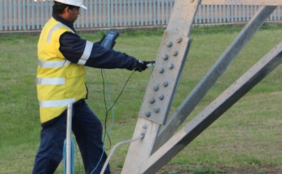
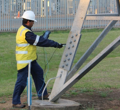
Injection testing is the most informative way of testing earthing system performance and safety. It aims to assess the actual performance of the earthing system by replicating a real fault (at a small scale) and measuring the effects. To achieve this, a circuit is established between the earthing system under test and a remote injection point. Ideally this circuit should reflect the actual fault supply circuit, which often requires an outage. If this is not feasible, post testing analysis is necessary to reflect the actual fault scenario.
The effects are made measurable, even on live systems, by injecting at a frequency away from power system frequency and using frequency-tuneable instrumentation. The test is referred to as a Low Current, Off Power Frequency Injection Test.
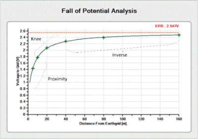
The test current, commonly between 2 and 20 amps, causes an Earth Potential Rise (EPR) at the earth grid under test, where the voltage of the soil at the earth grid rises with respect to the surrounding area. This EPR can be determined by the Fall of Potential (FOP) method, where the potential difference between the earth grid and the soil is measured at increasing distances away from the earth grid. The route and distance should be chosen to minimise measurement errors.
While test current is flowing in the fault circuit, measurements of actual touch and step voltages can be made. Also, hazards produced on other infrastructure such as telecommunications networks or pipelines can be measured. Selection of measurement locations requires careful consideration of typical contact scenarios, transfer mechanisms and capacitive and inductive effects as it is rarely possible nor valuable to measure every impacted location.
Further, the amount of fault current flowing in other earthing connections can be measured, including cable screens, OHEWs, LV neutrals, pipelines and other metallic infrastructure. This provides a clear picture of the entire earthing system rather than just focusing on the earth grid.
Measured currents, EPR and hazard voltages can be scaled to indicate the actual voltages experienced during a real power system fault. The resistance of the earth grid can also be accurately deduced.
Current injection testing is the only test to measure actual performance, but it can be complex and relatively expensive. It is recommended at commissioning, and at intervals of between 10 and 15 years, or when there are major changes to the power or earthing system or nearby infrastructure.
Three-Point Resistance Test
This test provides a measurement of the resistance of a simple earth grid. The test instrument is connected to the earth grid under test, and to a remote temporary electrode, and also to a second, intermediate temporary electrode. The test instrument passes a current between the grid and the remote point, and measures the resulting voltage between the grid and the intermediate point, and then calculates the implied resistance of the earth grid.
Three-point testing is quick and easy and can be a good indicator of any changes to the buried earth grid, but the results have limited meaning where there are auxiliary connections to the grid such as cable screens and OHEWs and the test does not provide any assessment of hazards for safety compliance. Mutual earth resistance (MER) and inductance can also significantly affect results if not considered effectively.
For these reasons, three-point testing is usually only recommended for very simple, isolated earth grids.
Loop Impedance Test
This test uses a modern ‘clamp-on’ meter to test the impedance of a circuit through available earth loops. A typical application is where an electrode is also connected (via an accessible cable) to another electrode or buried earthing element. The meter is clamped around the interconnecting cable, and applies an EMF on the cable, simultaneously measuring the induced current in the cable. This provides a measurement of the impedance of the circuit.
Whilst this may at first seem similar to 3-point testing, it is important to remember that this test measures the resistance/impedance of the entire circuit, not just the earth grid or electrode under test.
Whilst relatively inaccurate, this test is very fast and inexpensive and can be an excellent indicator of problems, changes or damage, when results are tracked over time.
Where considered useful, loop impedance testing is recommended at intervals of between 1 and 3 years, where trending is often more important than the individual measurement.
Soil Resistivity Testing
This testing measures the resistivity of the soil in which the earth grid is (or is to be) buried. Soil resistivity, along with soil layering, has a direct relationship to the resistance of the earth grid and therefore is very important during the design stage.
There a number of test methods, of which the most practical is usually the Wenner method. In this test, four temporary electrodes are placed in a line with equal spacing. A specialised test instrument passes current between the outer electrodes and measures the resultant voltage between the inner electrodes. Often a reciprocal measurement is taken (current between inner electrodes, voltage between outer) and then the spacing between the electrodes is increased and the measurements repeated. The successive measurements provide an indication of the resistivity of the soil at increasing depths, allowing the engineer to develop a model of the soil, which could be homogenous, two or even three layers.
Modern test equipment makes this test relatively straightforward, but results can be significantly affected by induction, external infrastructure, electrode depth and contact resistance, and poor test practices. Therefore a good understanding and assessment of results during the test is essential.
Soil resistivity testing should be performed during the design stage, or if there is any uncertainty about existing soil models.
Continuity Testing
Continuity testing, or integrity testing, is one of the best indicators of the physical condition of the earthing system. It is used to measure whether items that should be connected to the earthing system are effectively bonded, and can quickly identify such problems as corroded connections, loose bolts, inadvertent connections or separations.
Adequate bonding is essential to ensure that personnel are working only on equipment that is effectively connected to the earthing system.
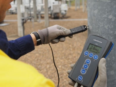
The test measures the small resistances between items of plant and the main earth grid. This test is especially important in large earthing systems where visual inspection of all conductors and connections is more difficult.
Selection of the appropriate test instruments and method is critical, since the test environment is subject to significant standing AC and DC voltages in the earthing system, induced voltages in test leads, relatively long distances between test points, and surfaces that can cause damage to test leads and therefore erroneous results. A test instrument using the four-wire test method is the most accurate, but should be checked for sufficient immunity to AC and DC noise. ‘Ground meters’, contact resistance meters, micro-ohmeters and multimeters all have limitations; an application-specific DC continuity meter is recommended.
With the right instrument and knowledge, continuity testing is relatively straightforward and is typically recommended at intervals of between 1 and 3 years.
Visual Inspection
Effective visual inspection is also extremely beneficial in assessing condition and changes to the earthing system. It typically involves checks of the presence, appropriate redundancy, suitability and visible condition of earthing conductors, connections, surface layer materials and connected equipment and is typically recommended at intervals of between 1 and 3 years.
Download PDF:
Safearth Technical Article – Earthing Tests – Making The Right Choice